Active Contour Panel
The Active Contour panel includes tools to create a group of paths, draw paths in Freehand or Snap mode, edit paths, and iterate selected paths. You can generate mesh surfaces that describe the segmentation target after the required number of paths have been added to a group. Groups of paths and generated meshes are added automatically to the Data Properties and Settings panel, while individual paths are retained in the Active Contour panel.
Choose Tools > Active Contour on the menu bar to open the Active Contour panel, shown below.
Active Contour panel

A. Path tools and options B. List of paths C. Settings D. Iteration controls
The tools available on the top section of the Active Contour panel let you create a group of paths, draw paths, and manually adjust paths with the Repulsor tool. The Path options available below the list of paths let you fit the current view to the selected path, as well as to copy or delete a path. If required, you can iterate selected paths to refine your selections.
You should note that path behavior is determined by the selected dataset and its settings, which provides the edge map (see Dataset Settings), and the selected snake settings, which provide the snapping behavior (see Snake Settings).
|
|
|
Description |
|---|---|---|
| Create group of paths |
|
Creates a new group of paths. Each group of paths will appear as a new item in the Data Properties and Settings panel. |
| Freehand mode |
|
Adds a new path in Freehand mode to the current group of paths. Do the following to draw a path in Freehand mode:
|
| Snap mode |
|
Adds a new path in Snap mode to the current group of paths. You use the Snap tool to create a path by simply dragging inside a feature on a 2D view. The contour line will automatically snap to the gradient that defines the edges of the targeted feature. Do the following to draw a path in Snap mode:
|
| Edit mode |
|
Lets you manually adjust the contour of a path with the Repulsor tool. To adjust the contour:
|
| Look at path |
|
Fits the current view to the selected path. If required, the orientation of the view will be updated to match the orientation of the selected path. |
| Copy path |
|
Copies the selected path to the current view. |
| Delete |
|
Deletes the selected path. |


All of the paths that are included in the currently selected group of paths are listed in the Active Contour panel. Selected paths can be iterated, as well as included for generating mesh surfaces.
You can Ctrl-click to add paths one-by-one to a selection or you can Shift-click to add paths within a range. You can also press Ctrl + A on your keyboard to select all the paths in the group. You should also note that you can rename a path by double-clicking its title.
Settings for computing the edge map from the selected dataset, optimizing the snapping behavior of paths, and options for generating mesh surfaces are available in the tabs at the bottom of the Active Contour panel.
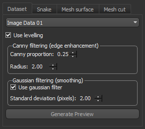
The settings available on the Dataset tab can be used to optimize the edge map computed from the selected dataset. You can evaluate computed edge maps by generating single-slice previews.
Dataset settings
|
|
Description |
|---|---|
|
Drop-down menu |
Lets you choose the dataset from which the edge map will be computed. You can use window leveling values, Canny filtering, and smoothing to optimize the edges that define object boundaries. |
|
Use leveling |
If selected, the current leveling values will be used to control edges. Values below the minimum value of the window width and values above the maximum value of the window width will capped to the selected range. |
|
Canny filtering |
Lets you proportionally enhance the edges of the selected dataset with Canny filtering. The Canny edge detector is an edge detection operator that uses a multi-stage algorithm to detect a wide range of edges in images. Canny proportion… Determines what proportion of Canny filtering will be included in determining the image gradient. At a setting of 0, no edge enhancement will be applied, while at a setting of 1.0 only the result of Canny filtering will be used in the edge map. For best results, you should adjust the Canny proportion gradually or modestly. Radius… Determines the size of the smoothing filter used in the first stage of the Canny algorithm. Smaller sizes cause less blurring and allow detection of small, sharp lines, while larger sizes causes more blurring and are more useful for detecting larger, smoother edges. |
|
Gaussian filtering |
If selected, Gaussian filtering will be applied to smooth the edge map of the input dataset. The effect of applying the Gaussian filter is to blur an image and remove detail and noise. Standard deviation (pixels)… Determines the standard deviation of the Gaussian used for smoothing differences in intensities. The greater the value, the stronger the blur will be. |
|
Generate Preview |
Generates a one-slice preview of the currently selected view that lets you evaluate the computed edge map and your Canny filtering and Gaussian filtering settings. Previews will appear as new items in the Data Properties and Settings panel. You can view a preview, shown below, by changing its visibility in the panel.
|

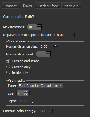
The Snake settings, which include points distance, normal search options, and path rigidity, help control the internal forces that resist deformation when paths are iterated. The Snake settings also include the energy minimization criteria.
Snake settings
|
|
Description |
|---|---|
|
Current path |
Indicates the path currently selected in the path list. |
|
Max iterations |
Lets you set the maximum number of iterations that well be performed. Iteration will stop automatically when the minimum delta energy criteria is met. |
|
Reparametrization points distance |
Determines the distance (in screen pixels) when drawing paths and is used by the Repulsor tool to push path points. Increasing this parameter will result in downsampling and a smoother path, while decreasing this parameter is recommended for following more angular features. NOTE This parameter may need to be reduced if mesh surfaces are unintentionally closed after generation. |
|
Normal search |
Determines how the application will search for the image gradient, as a function of the number of points and distance between the path location and image edges. Normal distance step… Determines the step distance (path location to edge) to search from. Normal step count… Determines the number of points in the normal direction from the path that will be used to search for the highest value in the edge map. Outside and inside… If selected, searches for the highest value in the edge map in the normal direction to the path will be performed both outside and inside of the selected path. Outside only… If selected, searches for the highest value in the edge map in the normal direction to the path will be performed only outside of the selected path. Inside only… If selected, searches for the highest value in the edge map in the normal direction to the path will be performed only inside of the selected path. |
|
Path rigidity |
These settings let you control the smoothing of paths during iteration. Type… Lets you choose between Fast Gaussian Convolution and sin(x)/x Convolution as the method to control smoothing. Size... Determines how many neighbors will be used to smooth the path. At a setting of 7, 3 neighbors on each side of a point will be used to average the path. Sigma... Increasing the standard deviation will result in smoother paths after iteration. At a value of 0, no smoothing will be applied to self and neighbors. |
|
Minimum delta energy |
Determines the value at which the minimum delta energy criteria is met and continued iteration will not move the path. The minimization is done implicitly in the shape energy and explicitly in the image energy. At a setting of 0.01, a difference of 1% would be required to move the path points during iteration. |
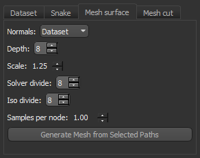
Lets you chose the settings that will be applied to generate a mesh surface from all selected paths in the paths list. You should note that unselected paths will be excluded from all calculations.
Important considerations for generating mesh surfaces are the reparametrization points and the direction of the normals. Consult the referenced publication for more information about the implementation of the Poisson surface reconstruction algorithm.
Mesh surface settings
|
|
Description |
|---|---|
|
Normals |
Lets you choose the direction of the normals — Dataset or Path Plane — that will used to generate the mesh surface. NOTE In general, if information about edges are available, then selecting the normals of the dataset is recommended. If the quality of the dataset is poor or if it is very noisy, then Path Plane might be a better choice. |
|
Depth |
Lets you choose the maximum depth of the tree that will be used for generating the mesh surface. Smaller depth values will result in lower resolution meshes. |
|
Scale |
Lets you choose the ratio between the diameter of the cube used for reconstruction and the diameter of the samples' bounding cube. |
|
Solve divide |
Lets you choose the depth at which the solver is used to solve the Laplacian equation. |
|
Iso divide |
Lets you choose the depth at which the ISO surface is extracted. |
|
Samples per node |
Lets you choose the minimum number of sample points that should fall within an octree node. For noise-free samples, a value between 1.0 and 5.0 may work well. For noisy samples, a value between 15.0 and 20.0 may be needed to provide a smoother reconstruction. NOTE Octrees help organize the points of a 3D object very efficiently. An oversimplified way of explaining it is to imagine slicing up your point cloud into eight equal cubes (octants). That is the equivalent to an Octree depth of 1. To get to a depth of 2, slice up each octant into eight more octants (totaling 64 octants). The higher the number the Octree Depth parameter is set, the more importance is put on each point. This will also mean exponentially longer mesh times. The lower the Octree Depth number, the less importance each individual point has. |
References
[1] Poisson Surface Reconstruction for VTK, David Doria and Arnaud Gelas, March 19, 2010, Rensselaer Polytechnic Institute, Troy NY and Harvard Medical School, Boston MA.
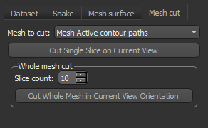
Options in Mesh cut tab are available after an initial mesh surface is generated. These options let you cut a single slice from the selected mesh on the current view or to cut the whole mesh into a series of paths. Cutting a mesh surface may be required to generate paths in an additional orientation(s) if mesh surfaces are initially unsatisfactory.
You can also import any other mesh, such as a reference STL mesh generated from AutoCAD, as the input mesh.
Mesh cut settings
|
|
Description |
|---|---|
|
Mesh to cut |
Lets you choose the mesh to cut. |
|
Slice count |
Lets you choose the number of cuts that will be performed on the selected mesh surface when you cut the whole mesh. |
A number of configured actions and keyboard shortcuts are available for creating and editing paths with the Active Contour tools. The default settings for these actions are listed in the following table.
|
Action |
State |
Key |
Mouse |
|---|---|---|---|
|
Copy current path on current slice from Draw path (active contour) |
ORSStateDensePath |
C |
|
|
Copy current path on current slice from Edit mode (active contour) |
ORSStateEdit |
C |
|
|
Copy current path on current slice from Snap tool (active contour) |
ORSStateSnapTool |
C |
|
|
Decrease Repulsor radius (active contour) |
ORSStatePathRepulsor |
Left Ctrl |
Mouse wheel down |
|
Draw path for active contour (active contour) |
ORSStateDensePath |
|
Left mouse |
|
Draw path using Snap tool (active contour) |
ORSStateSnapTool |
|
Left mouse |
|
Increase Repulsor radius (active contour) |
ORSStatePathRepulsor |
Left Ctrl |
Mouse wheel up |
| Iterate selected paths from Draw path (active contour) | ORSStateDensePath | I | |
| Iterate selected paths from Edit mode (active contour) | ORSStateEdit | I |
|
| Iterate selected paths from Snap tool (active contour) | ORSStatesnapTool | I |
|
|
Open the Active Contour panel |
|
|
|
|
Repulse a path (active contour) |
ORSStatePathRepulsor |
Left Ctrl |
Left mouse |
|
Select and look at next path in group in Draw path (active contour) |
ORSStateDensePath |
Down |
|
|
Select and look at next path in group in Edit mode (active contour) |
ORSStateEdit |
Down |
|
|
Select and look at next path in group in Snap tool (active contour) |
ORSStateSnapTool |
Down |
|
|
Select and look at previous path in group in Draw path (active contour) |
ORSStateDensePath |
Up |
|
|
Select and look at previous path in group in Edit mode (active contour) |
ORSStateEdit |
Up |
|
|
Select and look at previous path in group in Snap tool (active contour) |
ORSStateSnapTool |
Up |
|
|
Switch to Draw path (active contour) |
|
|
|
|
Switch to Edit mode (active contour) |
|
|
|
|
Switch to Snap tool (active contour) |
|
|
|
|
Temporary switch to Repulse mode from Draw path (active contour) |
ORSStateDensePath |
Left Ctrl |
|
|
Temporary switch to Repulse mode from Edit mode (active contour) |
ORSStateEdit |
Left Ctrl |
|
|
Temporary switch to Repulse mode from Snap tool (active contour) |
ORSStateSnapTool |
Left Ctrl |
|
See Configurable Actions for information about modifying the default actions for the Active Contour tools.